
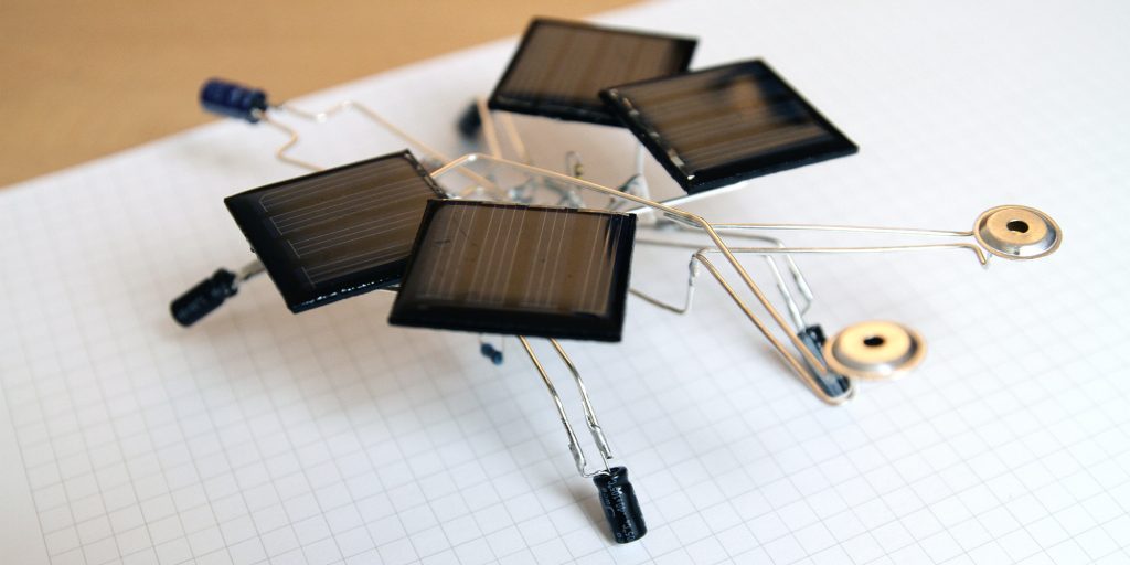
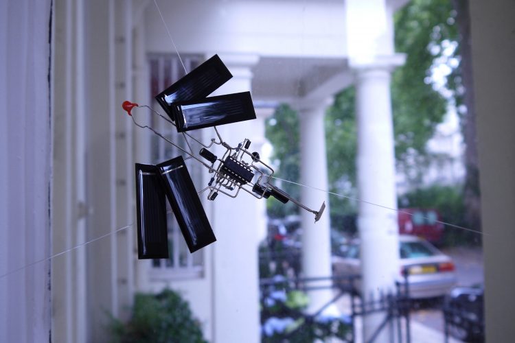
Make your own solar singing insect. © Davide Bevilacqua and Veronika Krenn
To usher in the spring, Veronika Krenn and Davide Bevilacqua, who first impressed us with their electro-bestiary, share their recipe for creating a singing insect.
We loved their singing bestiary made from 3D electronic circuits at the Unconscious Archives festival. In the exhibition Emotion + the Tech(no)body at Austrian Cultural Forum London, their insects created a soundscape of tiny noises that change over time, according to the light conditions and the presence of human beings.
We asked Davide Bevilacqua and Veronika Krenn, two artists based in Linz (Austria), to share their recipe. In this tutorial, Davide and Veronika explain how they produce their sound objects, step-by-step.

Time
The production of one insect takes around 5 hours:
– 30 minutes to decide how the object should look like and arrange the initial components;
– a minimum of 30 minutes to design the sound circuit (this can take much longer if you are not entirely satisfied);
– 2 hours and 30 minutes to solder the insect.
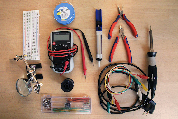
Tools
– Breadboard + flexible jumper wires
– Alligator clips
– Directional table lamp
– Multimeter
– Small pliers and wire cutters
– Soldering iron + desoldering tools
– Helping hand
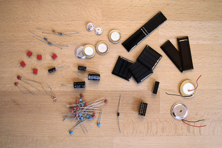
Materials
The following materials are needed for this tutorial. Other components can be used to create a different shape or sound.
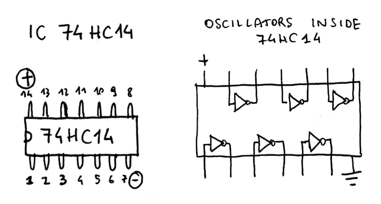
– 1x IC 74HC14
– 1x DIP 14 IC Socket
– 1mm-thick copper wire
– 4x square 30x30mm solar panel (2V 45mAh 0.09W). There are many sizes available online; removing the ones of some other toy is also an option.
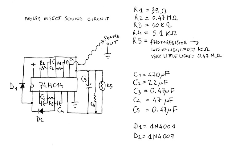
– assorted resistors (we use 1x 0.47 MΩ, 1x 19kΩ, 1x 5,1Ω, 1x 39Ω and one photoresistor)
– assorted capacitors (2x 0.47 μF, 1x 22 μF, 1x 47 μF, 1x 470 μF)
– diodes (1x 1N4001, 1x 1N4007)
– 2x small piezo transducers. Many sizes and cases available online, the ones with aluminum cover are louder, easier to solder, more resistant and aesthetically more interesting. According to their size, piezo transducers reproduce various frequencies at different loudness.
Cost
– around €20 (less if some material is already available or can be recycled from toys)
Step 1 – Shape and appearance
Bug, butterfly, bee, spider… There are plenty of beautiful insects! Look up some reference pictures and think which final shape you would like for your insect.
Arrange the solar cells according to the animal’s structure. Remember, solar cells are going to be a flat, visually dominant component of the insect. They function quite well as the wings or the body. Your choice!
To test the power supply, connect the solar cells in series with the alligator clips. Be sure to connect the “+” of one solar cell to the “–” of the next one.
Now, place the solar panels under a fairly strong light and, using the multimeter, check how much voltage is generated. The panels should not generate more than 7 Volts—that is the maximum voltage that the 74HC14 chip can support. If the voltage is too high, consider removing one or more solar cells from the series. If you plan to install the insect anywhere with direct sunlight, test the solar panels on a sunny day, close to a window.
Once you have found the right arrangement for the solar cells, solder them together using copper wire to build the structure. Before soldering, cut the copper wire and give it the desired shape.
Step 2 – Sound design
Once the voltage supply is ready, it is time to design the sound circuit.
We use the integrated circuit 74HC14, a “Schmitt trigger”. This type of IC compares electric signals and returns a digital output (0 or 1). With the right components, these ICs behave like a sound oscillator and produce square waves.

The circuit developed for this insect is based on a variation of the one produced by the Austrian artist Reinhard Gupfinger for his work Sound Tossing.
Each 74HC14 chip has inside six oscillators. It is not necessary to use all of them, but more will make the final sound more interesting. In the circuit we produced, the six oscillators are paired in couples: two of those pairs produce audible sounds according to the amount of light, while the third one produces slow rhythmic pulses. These three couples are connected together through two diodes and one audio filter.

To generate a different sound pattern, you can change some of the components we used or start a new circuit from scratch.
The sound can change radically according to the amount of energy and the type of loudspeaker or transducer that you will use. Already since the prototyping phase, we recommend using the same electronic components which will be integrated into the insect. Connect the solar cells that you soldered as the power supply for the new circuit, as well as the chosen piezo transducer as sound output.
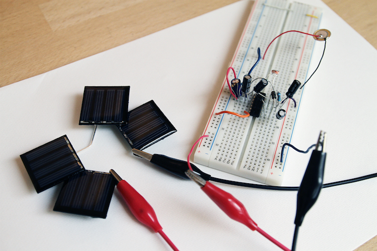
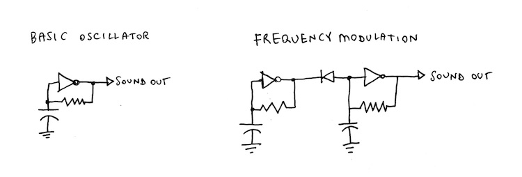
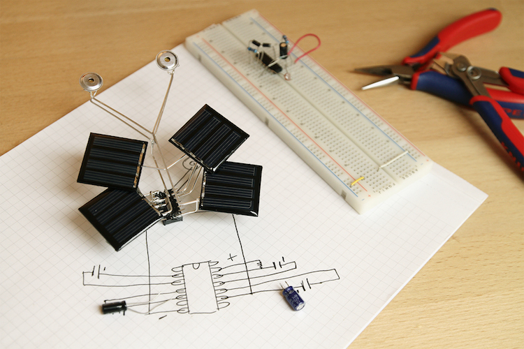
Build the circuit on a prototyping breadboard. With only one resistor and one capacitor, the 74HC14 can generate a stable oscillation, but more interesting sounds will emerge when also diodes, potentiometers or photoresistors are connected. Since each component contributes to the generation of a precise frequency, the oscillator can be made slower by using larger capacitors or larger resistors. To make it oscillate faster and therefore produce a higher tone, use smaller capacitors or smaller resistors.
Another solution for producing a dynamic sound is to modulate one of the oscillators through the output of another one, creating some “pairs”. This is a good strategy to produce a variable soundscape—combined together, one oscillator gives the rhythm, the other gives the frequency.


Forget the rules! This kind of circuit is meant to produce interesting sounds, rather than be “electronically correct”. In other words—if it sounds weird, that’s great!
Step 3 – How to rebuild all this?
Once you are happy with the sound you produced, it’s time to build the insect by soldering together the components you used. Before taking apart the circuit on the breadboard, carefully document the circuit schematic. Draw each connection, measure the value of every component, and note it down on paper.
The circuit is defined: you can now organize the visual appearance of the insect.
Imagine how the insect should look like and in which position, as well as which “visual role” could take each of the components. Keep in mind that like the solar cells, the IC will also have an important position in the object, as each component will be connected to it. Moreover, components with similar colors and shapes can be organized with “similar roles”, which can possibly relate to what the electronic component does. For example, photoresistors can be the eyes of the insect, while capacitors its legs.
Finally, components with very thin copper legs should stay closer to the IC, whereas “thick” ones can occupy distant positions. Thin-legged components will reinforce the copper-wire structure of the insect from the risk of deforming.
Remember: sketching these thoughts on paper will be very helpful while soldering.
Step 4 – Start soldering!
In the soldering phase, try to solder the extremities of components and wires as quickly as possible; otherwise, some parts may de-solder while you try to attach something. For the same reason, before soldering each next bit, leave enough time for the whole structure to cool down.
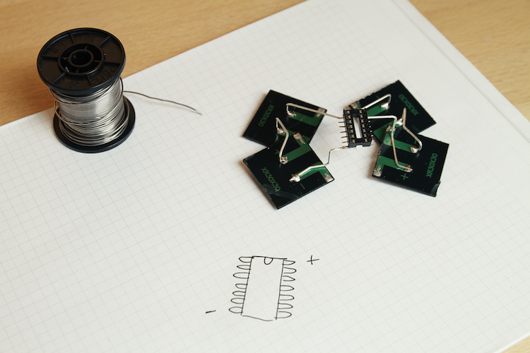
Connect the IC socket (DIP 14) to the solar cell, being careful to correctly match the voltage input of the chip with the positive side of the cells series. Afterward, disconnect one component at the time from the prototyping board, mark its original position on your paper schematic and solder it right away.
According to the visual plan of the insect, proceed with the components that occupy distant positions from the IC socket, for example, the piezo transducers or the capacitors.
Use the 1mm-thick copper wire to “extend” the legs of the components and reach the desired positions. In case the component’s legs are too long, trim them before soldering the component to the copper wire.
Finally, after everything has been attached, take the IC out of the breadboard and insert it into the IC socket, again paying attention to the correct direction.

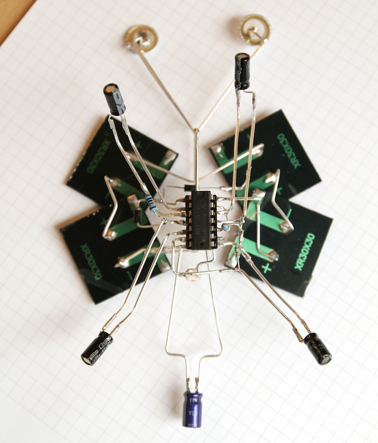
Now, once exposed to light, the insect should produce (approximately) the sound that you designed. If something does not work, or the sound is radically different, check each component and copper wire, comparing it with the schematic drawn before.
Here it sings:
More info on Davide Bevilacqua and Veronika Krenn
If you make your own solar singing insect by following Davide and Veronika’s tutorial, send us a photo or video, we’ll make a gallery!