

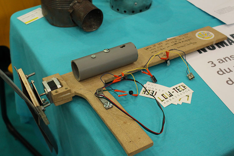
A pocket wind turbine that costs less than €15 . © Low-tech Lab CC-by-SA
#Fablab Festival. The Low-tech Lab presented in Toulouse a wind turbine made from salvage materials. And it only costs €15. Tutorial.
The Low-tech Lab is a collaborative research and documentation program aiming to spread and promote low-techs such as the wind turbine it presented on its stand at the Fablab Festival in Toulouse. With lower power than industrial wind turbines, it can be used to charge a phone, light up LEDs, activate a small pump, thanks to the few watts it produces… Here is the tutorial.

Equipment
– A wooden board (10mm thick minimum);
– A metal slab (2mm thick minimum);
– A step motor (salvage: printer/photocopier motor) ;;
– A PVC tube (diameter between 50mm and 100mm) ;
– A few woodscrews;
– 2 voltage rectifiers;
– A capacitor and a voltage regulator (LM7805 type for 5V) ;
– A USB connector;
– A plastic holder for electrical components;
– A soldering iron (+ tin and electrical wiring);
– A wood and metal saw;
– A screw-gun;
– A voltmeter and alligator clips;
– Cutting pliers.
Step 1: preparation of the blades and the aileron
For the blades, cut out a 35cm long PVC tube. Cut the tube across its length into 4 identical parts. Sand the edges of each blade: the leading edge must be curved and the trailing edge sharpened. Drill two holes at the base of the blades (one 10mm from the base and the other 30mm from the base).

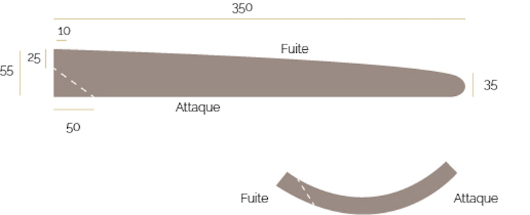
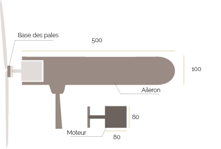
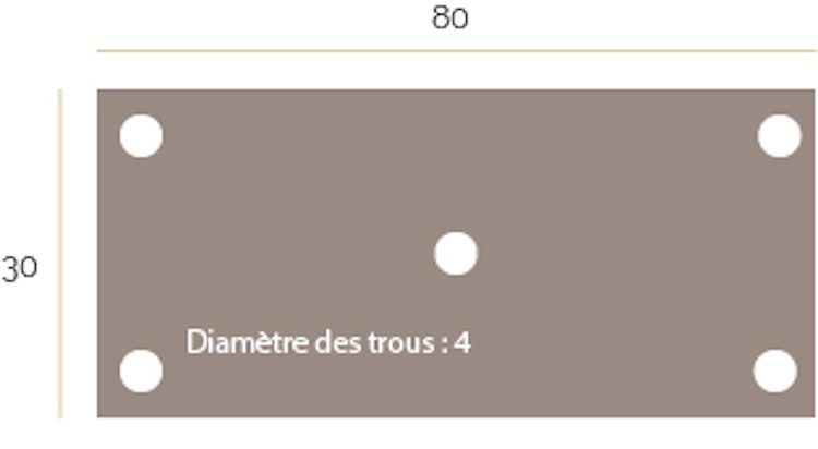
In the wooden board, draw and cut out the aileron (as shown below). In the same board cut out a square the size of your motor (here 80x80mm). It will serve as a base for the blades. On the aileron, mark the space for the motor so that it can be fitted by force in the shape. Sand the edges of the aileron for better aerodynamism.

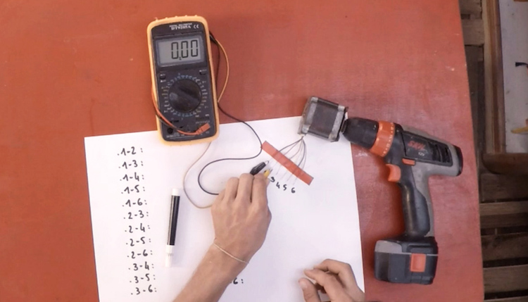
Step 2: preparation of the motor
Cut the six wires of the motor, strip and twist them. With a screw-gun, a voltmeter (set on “alternative”) and alligator clips, test and note the voltage of each pair of wires (cf. photo). Select the two pairs of wires with the highest output voltage, they will be used for the electrical circuit.

Cut the 80X30mm metal slab and drill a hole in the center and a hole in each corner. Solder or fix the central hole of the slab to the motor shaft.

Step 3: the electrical circuit

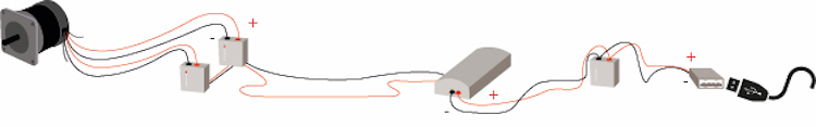
Rectifiers. At the output of the motor, you get alternating current. Yet, to charge a battery or switch a light on, you need direct current. For that, you use two rectifiers: they “rectify” the voltage at the output of the motor. Each rectifier has four leads: the two central leads are the alternating terminals of the rectifier and the two external leads are the positive and negative terminals of the rectifier (the terminals are indicated on the head of the rectifier).
Solder the pair of wires at the output of the motor (selected during the previous step) to the alternating terminals of the rectifiers (a pair of wires per rectifier). Solder the negative terminals of the rectifiers with each other then solder the positive terminals of the rectifiers with each other.
The capacitor. The energy delivered by the wind turbine is not constant because the wind speed varies permanently. You therefore need to stock temporarily the overload in order to be able to redistribute it in a constant manner. For this, you use a capacitor.
At the output of the rectifier, solder the negative terminal to the terminal of the capacitor (the shortest lead) and solder the positive terminal to the terminal of the capacitor (the longest lead). If the leads of the components are too short to solder together, use electrical wires to link them up.

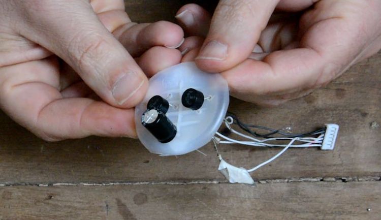
The voltage regulator. Each regulator is different: if you want a 12V output, for example, buy your regulator accordingly. To connect a USB port, we chose 5V (LM78xx type). The regulator has three different leads in frontal view: 1 input (+), 1 common (ground), 1 output (-).
Solder the negative terminal of the capacitor to the ground of the regulator then solder the positive terminal of the capacitor to the input of the regulator. Then, solder a red wire to the output of the regulator and a black wire to the ground. These will be the leads of your wind turbine, to which you can connect a battery, a light bulb or a USB port.
The USB connector. When you place your USB connector level with the plastic strip facing upwards, the right lead is the positive terminal, and the left lead the negative terminal.

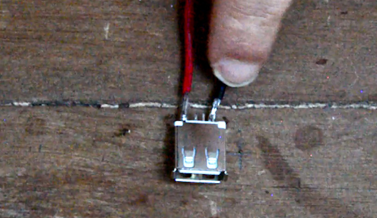
Solder the red wire on the positive terminal and the black wire on the negative terminal of the USB connector.
Step 4: assembly
Screw the blades on their base. Before tightening it to the maximum, check that you have the same angle between each blade. Finally screw the base of the blades onto the metal slab. Cover the motor and the electrical circuit with a bicycle wheel inner tube to protect them from bad weather.
Your low-tech wind turbine is ready for great adventure in the wind. The rotation of the wind turbine requires wind of a minimum of 10 to 15 km/h to start up. You can then plug any device equipped with a USB connection, but you will need to wait a few hours: count 5 hours of charging time for a phone battery with a moderate wind.
The tutorial of the Low-tech Lab on video (in French):
